
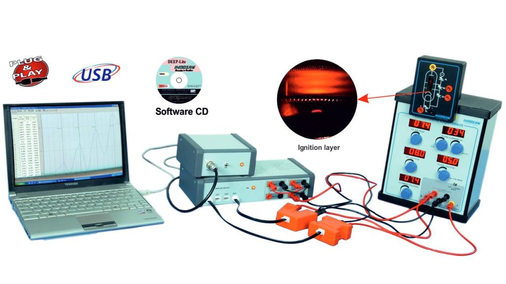
Franck Hertz Experiment
Item Code : SK087
Principle and Working:
The Franck-Hertz tube consists of an electron-emitting cathode, two mesh grids for accelerating electrons, and an anode plate for collecting them. It is filled with low-pressure gas. The mesh grids accelerate electrons, while the anode, held at a slightly negative potential, provides braking.At low accelerating potential, electrons undergo elastic collisions with gas atoms.
As the potential increases, inelastic collisions excite gas atoms, causing them to absorb energy. This reduces the number of electrons reaching the anode, creating dips in the plate current. These dips occur at fixed intervals, demonstrating quantized energy levels in Bohr’s atomic model.In the neon gas Franck-Hertz experiment, absorbed energy is released as red-orange photons, forming visible bands
- Automatic and Manual mode of operation.
- Ignition layers are visible on tube window.
- Voltage and Current sensors are auto ID.
- Free graph analyzer software.
- Individual 7 segment display for Filament voltage, control voltage, Grid voltage and accelerating voltage.
- Traco Power Supply for data logger and sensor.
- To observe the neon spectral bands in Franck- Hertz tube.
- To record the Franck-Hertz characteristic curve for neon (SK087 only).
- To study the effect of filament voltage and anode plate voltage on the characteristic curve.
- Franck Hertz Unit : Mode manual or Data Logging, Voltage 1.2-12V, Display 3½ digit LED Screen Grid (G ) Voltage 0- 80, Control Grid (G ) Voltage 0-10V, Filament Voltage 0-9V, 4mm safety socket used.
- Neon Tube : Dia. 130 x 26 mm, Filament voltage 6 – 9 V, Control voltage 9V, Accelerating voltage Max. 80 V Counter voltage 1.2 -10 V, 4mm safety socket, 4mm Plug.
- Data logger : I/P channels 4, 6 PIN BT connector, resolution 12 bit ADC @ 100 ksps, Analog I/P 0-5 V, O/P channels12 bit DAC, Analog O/P ± 12 V max 10 mA, Current booster 1A, Power connector 3PIN, DIN, USB cable.
- Power Supply : 220V, 50Hz AC, output ± 12 V, 3 PIN DIN.
- Voltage Sensor : ±10V, 4mm socket, 6 PIN BT connector.
- Current Sensor : ±100nA, 4mm socket, 6 PIN BT connector
| S.No. | Item Name | SK087 | SK090 |
| 1 | Current sensor 100 nA | 1 | — |
| 2 | Data logger | 1 | — |
| 3 | Flexible plug lead 25cm (black) | 1 | — |
| 4 | Flexible plug lead 25cm (red) | 1 | — |
| 5 | Flexible plug lead 50cm (black) | 3 | — |
| 6 | Flexible plug lead 50cm (red) | 3 | — |
| 7 | Franck Hertz unit | 1 | 1 |
| 8 | Neon tube assembly | 1 | 1 |
| 9 | Pen drive for experiment software | 1 | — |
| 10 | Power cord (main lead) | 2 | 1 |
| 11 | Power supply (traco power) | 1 | — |
| 12 | Sensor cable | 2 | — |
| 13 | Signal cable | 1 | — |
| 14 | Voltage sensor 10V | 1 | — |
Note : Computer/Laptop is not supplied with this setup.

 – Products