Home » College Physics Labs » Electronics » Study of Passive and Active Components with Deep Software S0589
Study of Passive and Active Components with Deep Software
Item Code : S0589
Principle and Working:
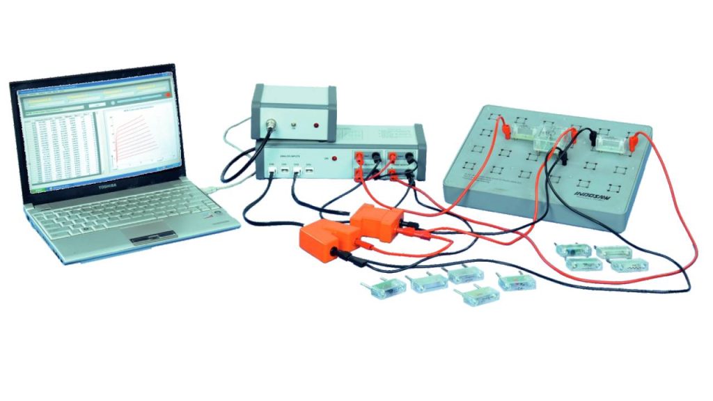
This experiment introduces the fundamental electronic components—resistor, diode, and transistor—and helps in understanding their basic electrical behavior using a Digital Electronics. Experiment Platform (DEEP). Resistors obey Ohm’s Law and are used to control current in a circuit. Diodes allow current to flow in only one direction, playing a crucial role in rectification. Transistors act as switches or amplifiers in electronic circuits. The DEEP system provides an integrated setup to study the voltage-current characteristics of these components efficiently and accurately.
Read More
- Auto identification of voltage and current sensors.
- High speed data transfer @ 100 kbps
- Free Data Logging graphical software.
- Real Time data acquisition and graph plotting.
- Programmable sampling frequency and Programmable delay in data acquisition.
- Automatic & manual mode of operation.
- Safe and clear view of electronics component in the transparent modules form.
- To study ohm’s law.
- To plot the V-I characteristics of Incandescent Lamp.
- To study the Rectifier Diode & its applications.
- To plot the V-I characteristics of a Light Emitting Diode.
- To study the Zener Diode & its applications.
- To study the NPN transistor characteristics.
- Data logger : 4 input channels, 6 PIN BT connector, resolution 12 bit ADC @ 100 ksps, Analog I/P 0-5 V, O/P channels 12 bit DAC, Analog O/P ± 12 V max 10 mA, Current booster 1A Power connector 3 PIN, DIN, USB cable.
- Power Supply : Input 220V, 50Hz AC, output ± 12 V, 3PIN DIN
- Voltage Sensor : ±1V, ±10V, 4mm socket, 6PIN BT connector.
- Current Sensor : ±1mA, ±10mA, ±100mA, ±1A, 4mm socket, 6PIN BT connector.
- Circuit Board : 4 mm safety socket, dimension 305 x 245 x 62mm, plastic mould, 4 rubber feet, templates holder.
- Resistance Modules : Transparent module 100Ω, 10Ω, 1kΩ, 10kΩ.
- Safe and clear view of electronics component in the transparent modules form.
| S.No. | Item Name | S0589 |
|---|---|---|
| 1 | Bridge Rectifier | 1 |
| 2 | Current sensor 1 mA | 1 |
| 3 | Current sensor 10 mA | 1 |
| 4 | Current sensor 100mA | 1 |
| 5 | Current sensor 1A | 1 |
| 6 | Data Logger | 1 |
| 7 | Digital Multi-meter | 1 |
| 8 | Diode Module (1N 4007) | 1 |
| 9 | Flexible Plug in Lead 100cm (Black) | 1 |
| 10 | Flexible Plug in Lead 100cm (Red) | 1 |
| 11 | Flexible Plug in Lead 25cm (Black) | 3 |
| 12 | Flexible Plug in Lead 25cm (Red) | 3 |
| 13 | Flexible Plug in Lead 50cm (Black) | 2 |
| 14 | Flexible Plug in Lead 50cm (Red) | 2 |
| 15 | Lamp Module | 1 |
| 16 | LED Module (Red) | 1 |
| 17 | Pen Drive for Experiment Software | 1 |
| 18 | Plug in Circuit Board | 1 |
| 19 | Power Cord (Main Lead) | 1 |
| 20 | Power Supply (Traco Power) | 1 |
| 21 | Resistance Box 5W, 5W | 1 |
| 22 | Resistance Module (1 kW) | 1 |
| 23 | Resistance Module (10 kW) | 1 |
| 24 | Resistance Module (100 kW) | 1 |
| 25 | Resistance Module (100 W) | 1 |
| 26 | Sensor Cable | 2 |
| 27 | Signal Cable | 1 |
| 28 | Transistor Module NPN (CL-100) | 1 |
| 29 | USB Lead | 1 |
| 30 | Voltage sensor 10V | 1 |
| 31 | Voltage sensor 1V | 1 |
| 32 | Zener Diode Module (3.9V) | 1 |
| 33 | Zener Diode Module (5.1V) | 1 |
* Additionally Required: Computer (not supplied with this setup.)